The simplest way to use WinVLL is with the USB Tower included in the RIS 2.0. However, if you don't have RIS2.0 you can use it with the VLL Probe.
Simply construct the VLL Probe, which is a simple electronic LED circuit, and use the "SoundVLL" mode of WinVLL.
First I wrote this page. Steve Arnold polishes up my ugly English. Thanks.
First get parts and material.
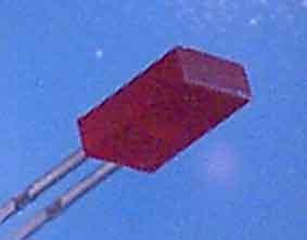
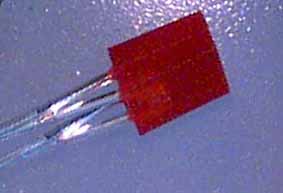
You can use any type of red LED, but since you'll be working with an audio (AC) signal and the MicroSCOUT sensor should receive both positive and negative phases, rectangular LEDs are recommended (they can easily be attached to one another to make a single assembly).
I used Stanley #BR5351
The LED is a type of diode, with polarity. However, the sound card can output only AC. Although this AC could be bridge-rectified via other diodes, the forward voltage drop after rectification would leave very little voltage to drive the LED.
Therefore, I decided to connect two LEDs in parallel, with reverse polarity to eliminate dropping the negative phase part of the signal. Since Light Emitting Diodes typically designate polarity by the length of its leads, a long and a short are connected together with solder.
Bond the two LEDs together with the quick-drying glue, before soldering.
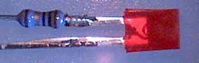
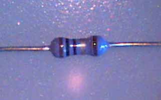
Solder the 10-ohm resistor to one of the leads.
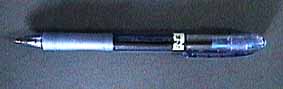
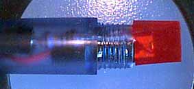
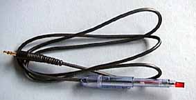
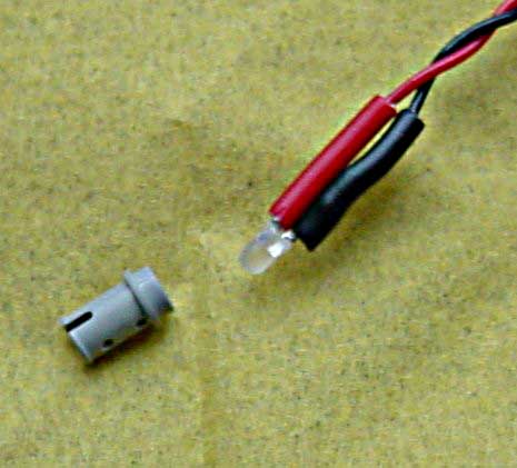
I used a broken ball point pen as the case for this probe.
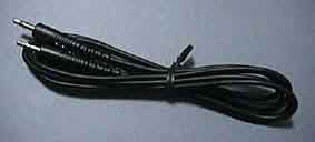
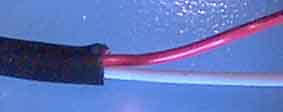
Cut to length and make a hole, and pass the cable through before assembling.
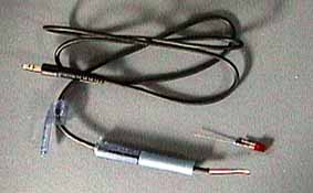
The cable shown here is 2 wires with a common shield line. Remove the outer sheath first and expose the shield.
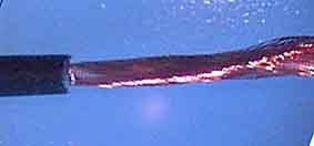
The shield is unnecessary and can be cut off entirely.
Solder the wires to the Light Emitting Diode assembly made previously.
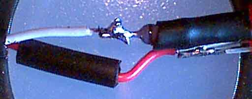
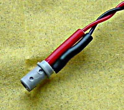
The sheath cut off previously can be used as a tube for insulation.
Put the assembly within the pen and fix with glue (you might want to test it before you glue it all together).
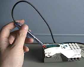
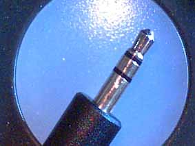
Set up WinVLL in SoundVLL mode, and plug the VLL Probe into the speaker jack of your PC sound card. Set MicroSCOUT to P-mode. Adjust your computer audio volume to low to begin with, and gradually increase it until you see good strong LED pulses.
Now hold the probe against the microscout's light sensor and try sending it codes.
If the Microscout successfully receives the light signal, it will respond with a high pitched beep. If it detects an error, a low beep will sound (or no sound).
Fabio Saradone tell me more easy method for make the probe, using 2 colors LED in a mold. He doesn't use resistor for SONY VAIO.
Back to "the cave of MindStorms

Last update